


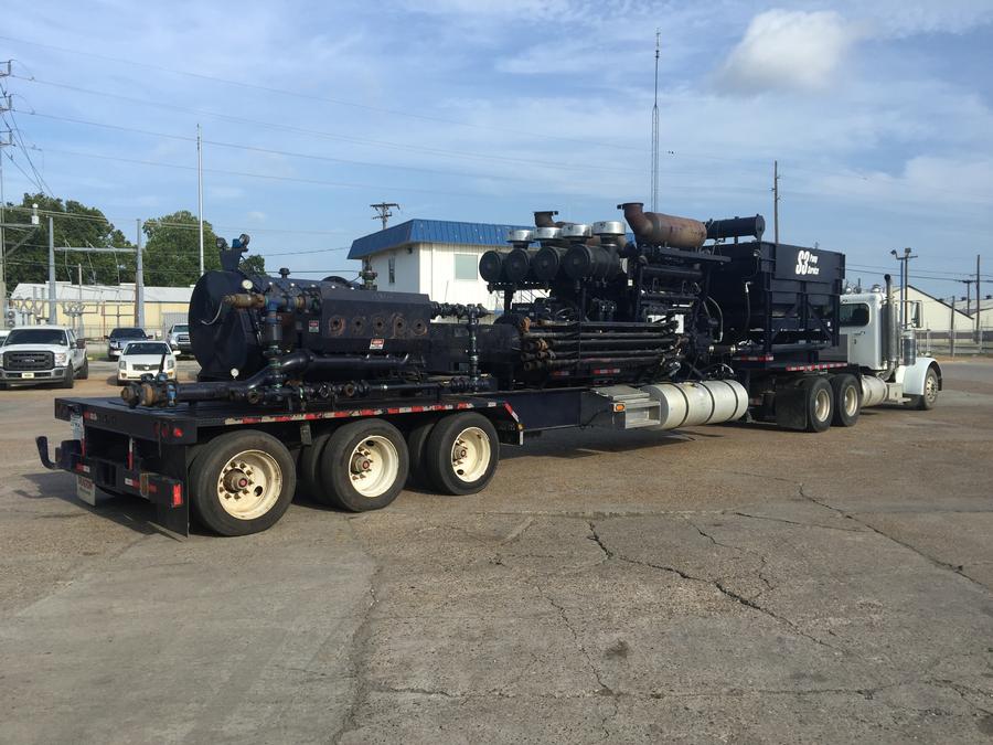
(6) 2013 DRAGON 3512 Frac Pump Packages
Sold - No Longer Available
Email for more infoWorked only in water business
2500HP CAT Engines & Transmissions
Very Good Condition
Located in Shreveport, LA
MAKE AN OFFER
Call to Inspect and Buy Today!!!
Call NOW! (800) 952-1973
Listing Details
FRAC PUMPING PACKAGE STANDARD SPECIFICATIONS 3512 SCAC-TH55-E70 REGION: USA
DRAGON PRODUCTS STANDARDS
Each standard unit features the following components
- Caterpillar 3212C SCAC diesel engine rated at 2500HP
- Caterpillar TH55-E70 7-speed petroleum transmission
- SPM QWS-2500SD Super Duty quintuplex pump
- Dragon controls with remote control
TRAILER
The support structure for the unit will be a Dragon Products Tridem Axle Skeletal Chassis.
Specification
- Trailer: Dragon Products Center Rail Skeletal Chassis
- Material: T-1 Steel
- Capacity: 85,000 lb
- Overall Length: 528 inch
- Back of Gooseneck to rear: 395 inch
- Overall Width: 102 inch
- Deck Height: 44 inch
- Rail Centers: 42 inch
- Wheelbase: 430 inch
- Gooseneck Length: 133 inch
- King Pin Setting: 18 inch
- King Pin Mounting Height: 50 inch
- Suspension: Watson Chalin TA-300 Tri-axle air ride, 51 inch spacing
- Axles: 25,000 lb, 77 ½ inch track, universal oil seals and bearings, open brake cams, auto slack adjusters
- Brakes: 16.5 x 7 inch Q brakes with 30/30 springs
- ABS: Bendix 4S/2M
- Hubs: 10 stud steel, hub pilot, cast outboard brake drums
- Wheels: Steel disc 8.25x22.5
- Tires: 255/70R22.5
- Landing Gear: Jost, 2 speed, 50,000 lb capacity
- Bumper: Oilfield style with tow eye
- Electrical: Sealed modular system with Peterson sealed beam LED lights.
- Misc: FMVSS approved relay emergency 2 line system with park brakes on all axles, Glad hands and electrical socket in middle of gooseneck. Suspension dump valve installed at drivers side front of rear fender.
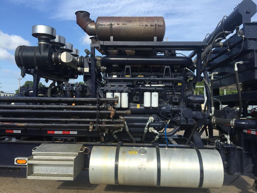
DECK ENGINE
Mounted on the deck of the trailer will be a Caterpillar 3512C SCAC diesel engine rated at 2500 BHP.
Specification
- Engine: Caterpillar 3512C SCAC
- Cylinders: 12
- Rated Power: 2,500 BHP at 1,900 RPM
- Air Filters: Caterpillar Supplied
- Exhaust System: Caterpillar Supplied
- EPA Rating: Tier 2
- Alternator: Caterpillar Supplied, 24VDC 60 Amp
- Starter: Single Hydraulic
- Fuel Filter: Caterpillar Supplied
- Oil Filter: Caterpillar Supplied
- Lube Oil: Caterpillar Supplied
- Batteries: Two, 12VDC, operating in series, 24VDC system
Support Parts
- Pre-Heater: Non-standard
- Fuel Tanks: Two, 200 USG aluminum round with crossovers
COOLING PACKAGE
A Horizontal cooling package will be installed on the gooseneck of the trailer.
Specification
- Radiator: General Thermal
- Aux Coolers: Lube Oil Cooler, Fuel Cooler, and Aux Hydraulic Cooler mounted beneath Radiator
- Fan: As specified by Caterpillar
- Fan Drive: Hydraulically driven, Closed Loop, Thermostatically Controlled
- Misc: Rubber shock mounts
TRANSMISSION
Mated to the Deck Engine will be a Caterpillar TH55-E70 Petroleum Transmission with integral torque converter. Driveline to pump will have a steel fabricated rotation guard.
Specification
- Torque Converter: Caterpillar integral to transmission
- Rated Power: 2,500 BHP at 1,900 RPM
- Flywheel: SAE 0 Wet
- Driveline: GWB 587.60
- Transmission: Caterpillar TH55-E70
- Ratios: 7 Forward, 0 Reverse
- Oil Filter: 2 – High pressure trailer mounted
- Lube Oil: Caterpillar recommended
- Controller: Caterpillar supplied transmission control system
- Cooler: 2 – Tube and Shell type mounted under radiator
- Misc: Mag pickup for driveline rotation, converted to bpm rate by system controls.
PUMP
Mounted on the rear of the unit will be a SPM QWS-2500SD, Super Duty or J-MAC Extreme Quintuplex pump complete with a 5 inch fluid end.
Specification
- Pump: SPM QWS-2500SD, Super Duty
- Fluid End: 5”
- Rated Power: 2,500 BHP
- Stroke: 8 inch
- Gear Box Ratio: 6.353:1
- Minimum Rate: 174 GPM at 1,500 RPM (engine speed)
- Maximum Rate: 1,096 GPM at 2,100 RPM (engine speed)
- Lube Oil (Power End): SPM recommended
- Grease Lube (Fluid End): SPM recommended
- Misc: Spicer 1950 Companion flange for driveline, zoomie manifold with 1” plugs for fluid removal
LUBE SYSTEMS
The pump’s fluid end is lubricated via a 24V grease system. Grease system is enclosed in fiberglass housing with a view through the front door. Grease is disturbed through an independent hose for each cylinder from the system pump. Unit is located on the driver side, ahead of the rear fender. The system is activated whenever the transmission output drive line rotation is above the preset minimum RPM.
The power end lubrication is hydraulically driven. The hydraulic pump is PTO driven off the transmission. A pump draws fluid from a 200 USG tank, mounted below and just ahead of the power end, and delivers it to the power end. A cooler is installed to prevent overheating of the oil. The flow through the cooler is controlled by a thermostatic valve allowing the oil to bypass the cooler until the minimum oil temperature is reached. They system includes the following; level sight eye, dual high flow filters (25 micron), temperature sensor (displayed on pump control data screen), pressure relief valve, pressure sensor (displayed on pump control data screen), suction line shut off valve. Nominal flow to be 50 GPM.
A drip tray is installed below the pump fluid end includes a ¾” inch drain plug located in each end.
Suction / Discharge Manifold
The suction manifold includes a 6” charge line to the pump with 6”-4” reducer and a 4” lateral off the side of the charge line. The rear of the 4” lateral line and the 4” reducer line are each fitted with a 150 LB ANSI flange located just ahead of the face of the bumper.
A 15k psi pressure transducer is mounted on the top of the fluid end.
Discharge manifold components and high pressure piping are not included.
Customer supplied components can be installed upon request.
HYDRAULIC SYSTEM
The unit’s hydraulics are powered from
(1) a wet kit mounted on a tractor (customer supplied and installed), The tractor wet kit powers the engine starter. Hydraulic connections to the tractor wet kit are made at the front of the unit at a level where and operator can reach standing on the ground. Ports in the front of the trailer are 1” female pipe. Hydraulic line connections are not provided.
(2) a PTO pad on the Caterpillar transmission, The PTO pad mounted system powers the SPM pump lube oil system
(3) a front drive installed at the harmonic balancer.
The front drive system powers the radiator cooling fan. The fan circuit is a closed loop variable speed system controlled by engine coolant temperature. It utilizes a 20 USG hydraulic oil reservoir. A secondary hydraulic oil cooler is mounted in the radiator to cool the fan drive system fluid. The fan drive fluid is filtered through a 10 micron return line filter. The tank includes the following: filler/breather cap, 2” fill port with dip stick, level sight eye, and suction line shut off valve.
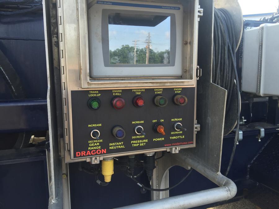
ELECTRONICS
The Frac Pumpers controls and instrumentation are installed in two areas on the unit. The local control panel is mounted at chest height on the driver’s side of the unit. The local control components are housed in a weather tight stainless steel enclosure. The panel is protected from vibration with cable isolators.
The remote control panel is mounted in a suitcase style enclosure and stored on the unit in the enclosed aluminum battery box located next to the local panel. Included with the unit is 200 feet of remote cable. The cable is stored on a fixed style wrap designed to hold 200 feet of cable and mounted to the side of the local panel protective support frame.
Local Control Panel
- Engine Diagnostic Light
- Engine Protection Light
- Local Control Touch Screen
- Engine Diagnostic Port (on engine)
- Main Power on/off Switch
- Engine Ignition on/off Switch
- Work Lights on/off Switch
- Remote Control Cable connection port
- Over pressure instant neutral system
- Emergency Shutdown Button
- Remote Control Touch Screen
- Cable Input Port
- Neutral Direct Button
- Throttle / Rate Control / Pump pressure controls and display
STORAGE
Top hinged lid tool box located on the passenger side of the trailer behind the fuel tank
PAINT
Paint specifications are detailed at the time of final submittal. Typical paint systems include steel grit blasting of all surfaces to SPF-6, epoxy primer and urethane color paint
DOCUMENTATION
Each unit is provided complete with two (2) sets of data and equipment manuals for the purchased components as available from and supplied by the component manufacturer. Sets will be paper copy with 1 set of electronic media provided if available. Hydraulic and electrical schematics are included.
Email for more info