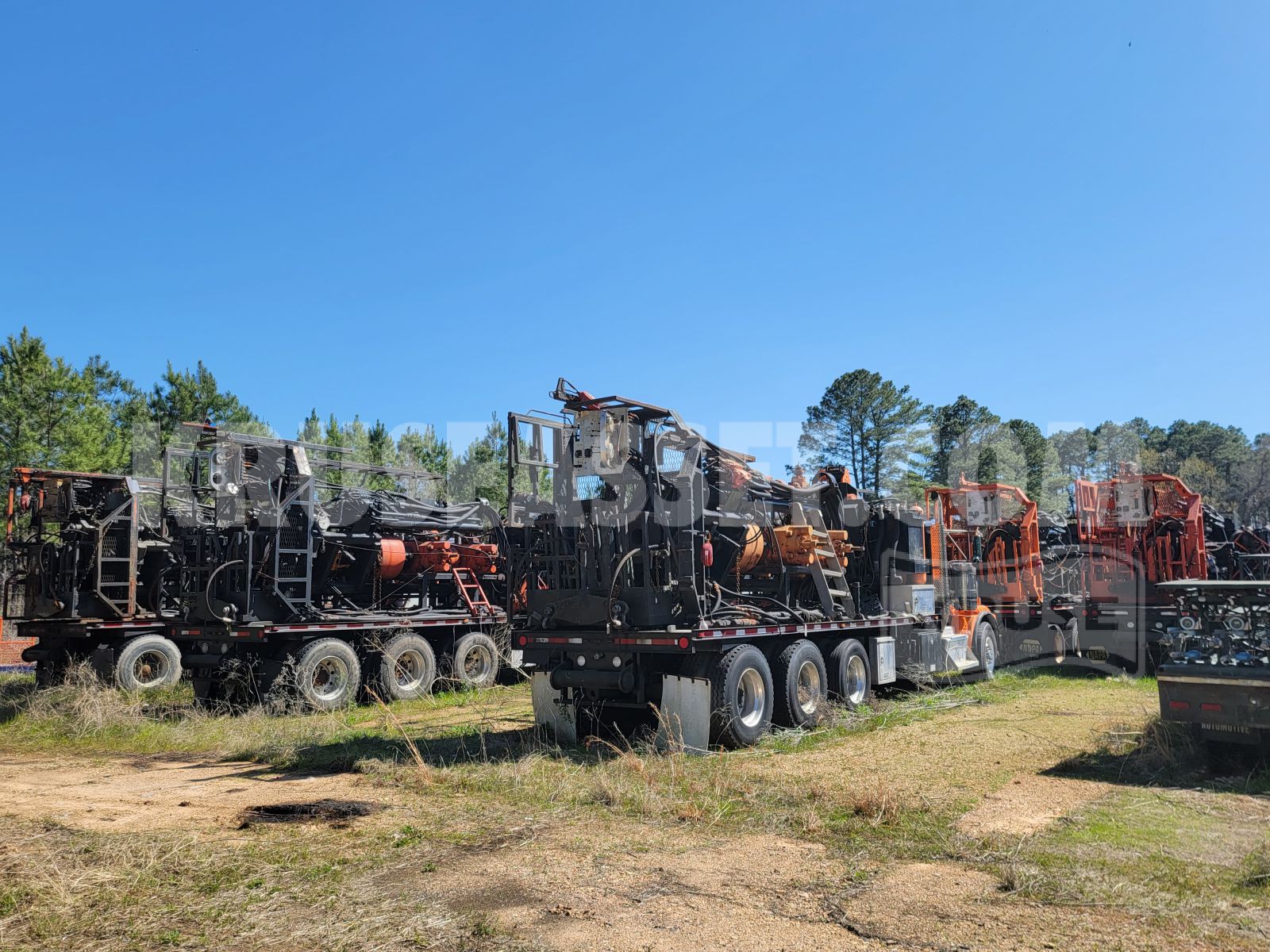
(2) 170K Hydraulic Rig Assist Snubbing Units for Sale
No Longer Available - Call for Inventory
Email for more info$275,000 Price Slashed to $199,000
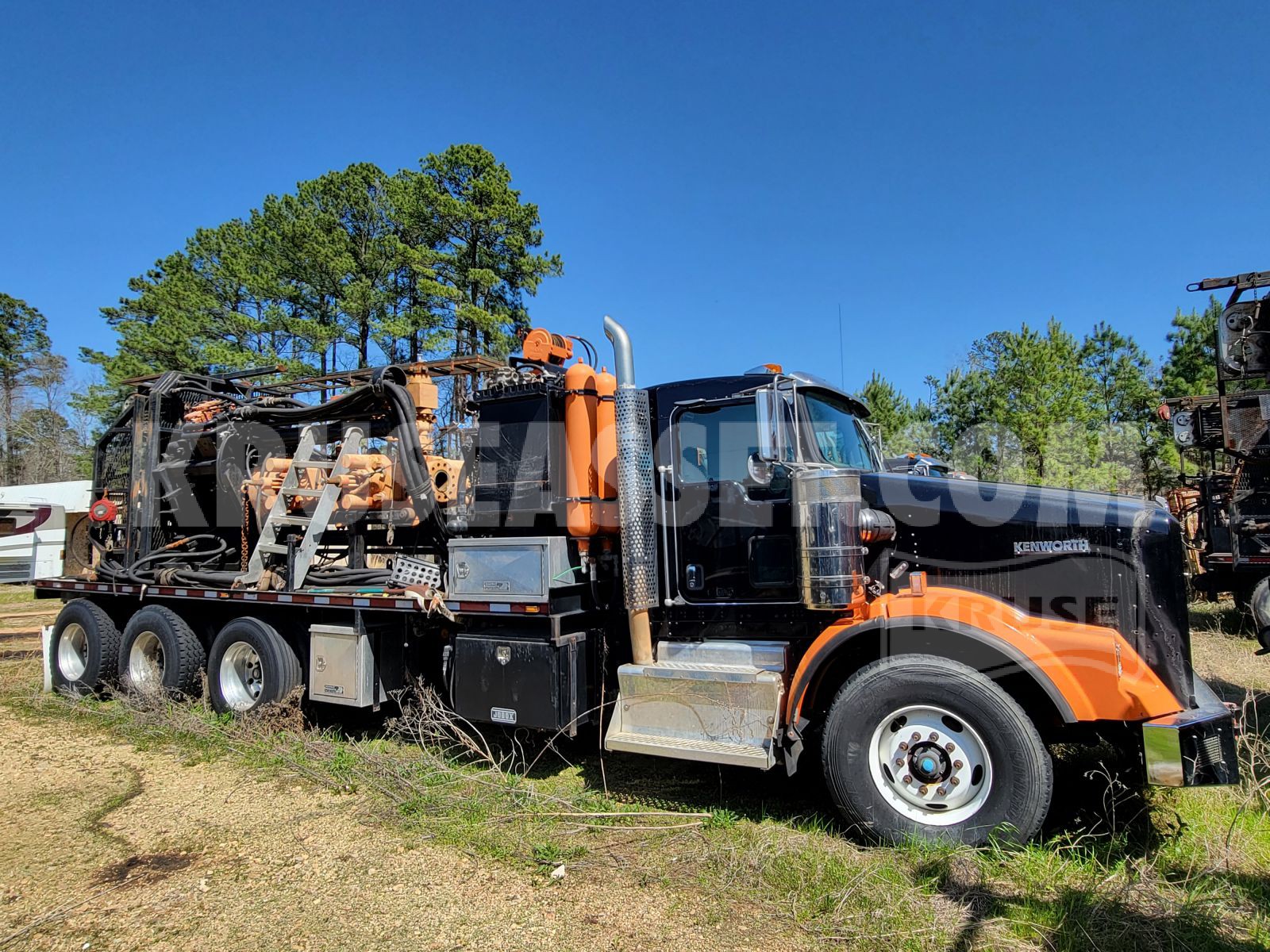
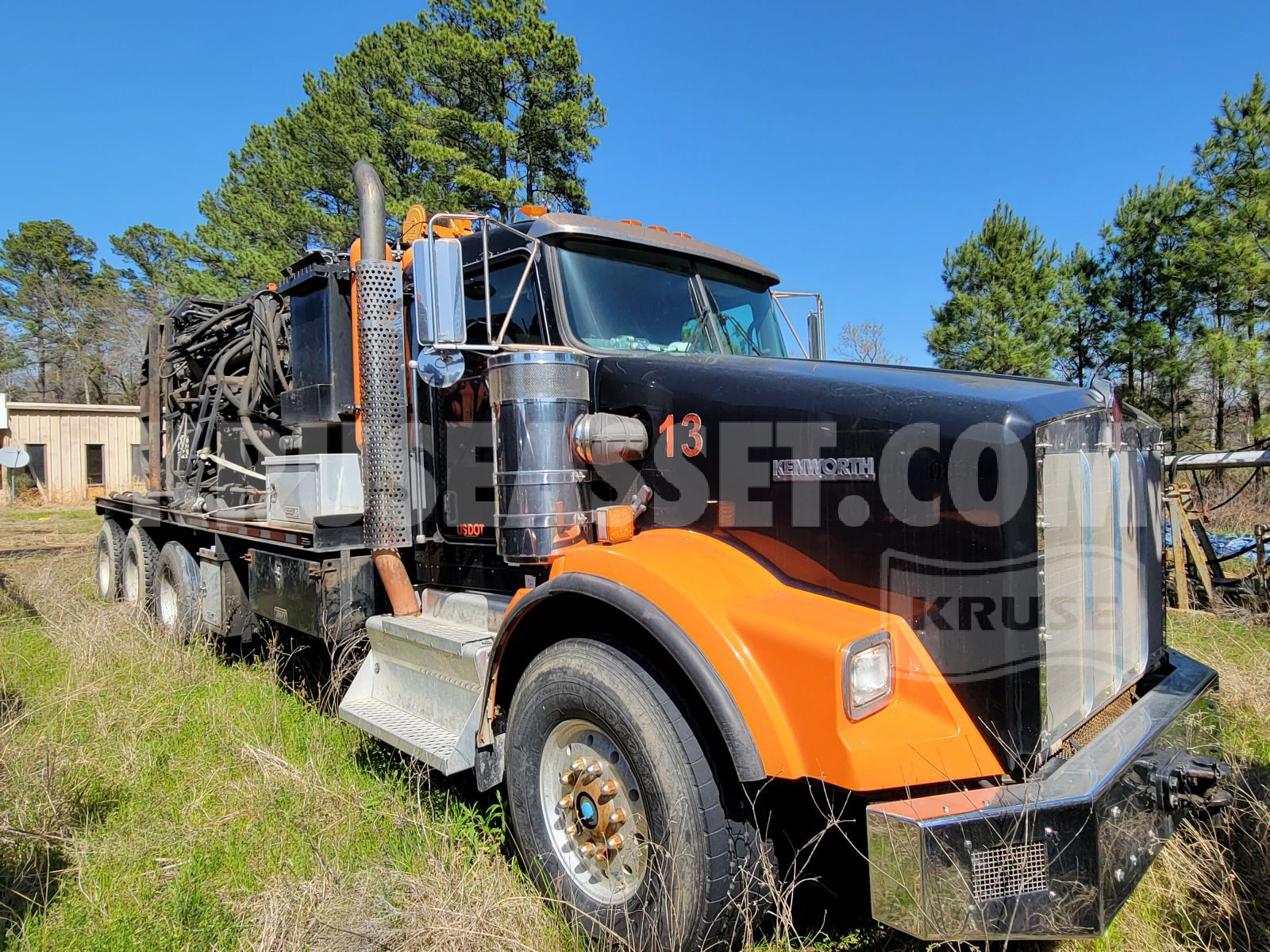
Kenworth Model T800 Trucks
Reconditioned & Working!!
Located in East TX
NOW ACCEPTING OFFERS
Call to Inspect and Buy Today!!!
Call NOW! (800) 952-1973
Listing Details
|
ST-01 |
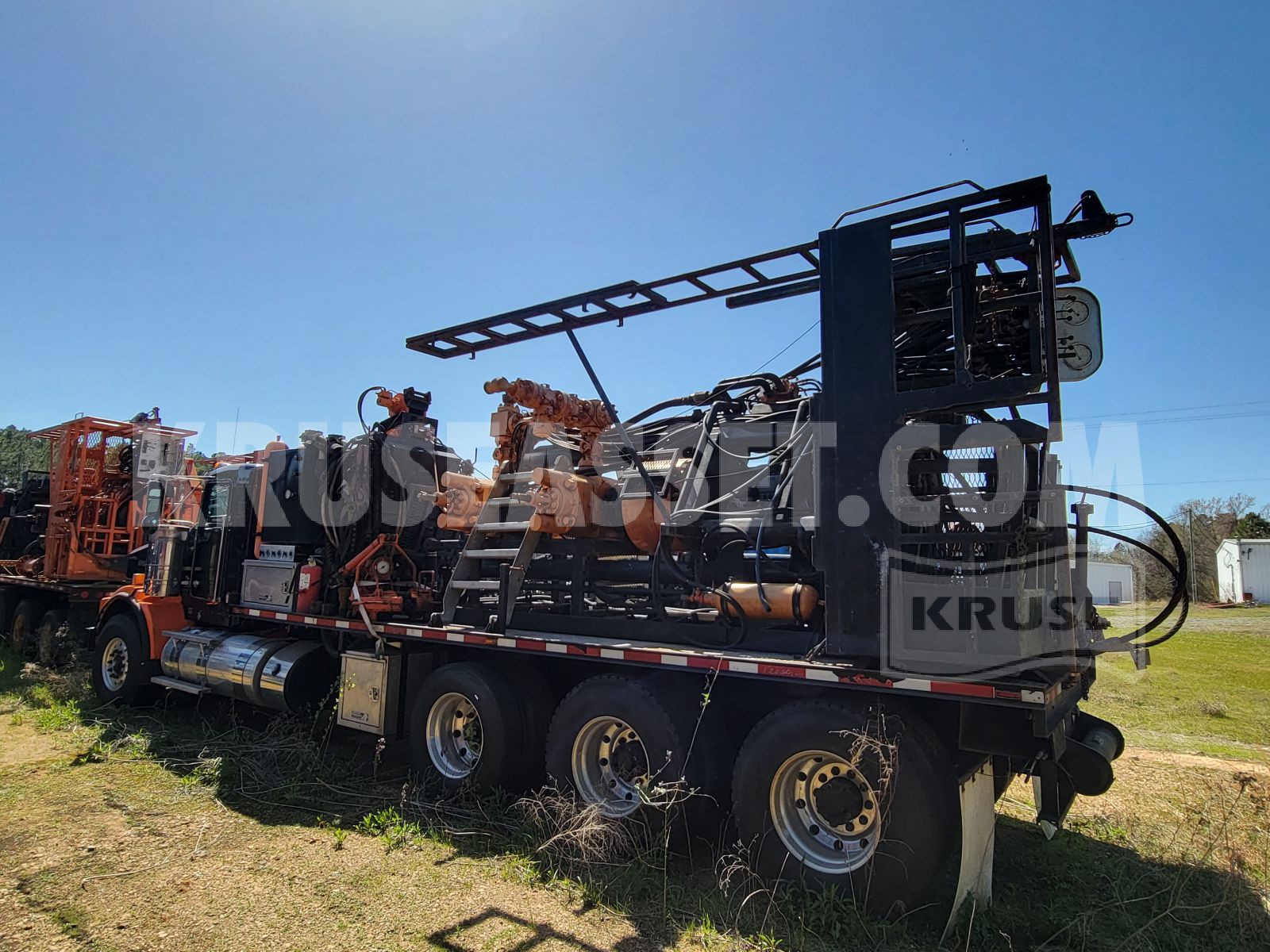
170K HYDRAULIC RIG ASSIST SNUBBING UNIT |
2013 KENWORTH MODEL T800 |
1NKDX4TX5DJ352793 |
26,143 |
2,832.4 |
7-1/16" 5,000 S/N 095 |
7-1/16" 5,000 S/N 094 |
7-1/16" 5,000 S/N 888 |
|
ST-11 |
170K HYDRAULIC RIG ASSIST SNUBBING UNIT |
2012 KENWORTH MODEL T800 |
1NKDX4TX1CJ310829 |
21,963 |
9,915.2 |
7-1/16" 5,000 S/N 116 |
7-1/16" 5,000 S/N 115 |
7-1/16" 5,000 S/N 1144 |
1.0 Scope
2.0 Snubbing Jack
This jack assembly is designed to push (snub) and pull (lift) pipe into and out of a dead/pressurized wellhead utilizing three (3) hydraulically operated 170k, 7-1/16” slip bowls. This assembly is designed to be used as both a Stand-Alone snubbing unit, and a Rig Assist snubbing unit. This assembly is designed to work in conjunction with the Annular BOP and 2 x BOP stripping rams. This assembly will consist of the following components:
- Jack Plate
- Passive Rotary
- Traveling Snubbing Slip Bowls
- Control Panel(s)
- Upper Work Platform
- Stationary Snubbing Slip Bowls
- Stationary Heavy Slip Bowls
- Jack Cylinders
- Annular Preventor
- Upper stripping Ram
- Bleed off/ Equalize Spool
- Bleed off/Equalize Plug Valves (1” ID)
- Lower Stripping Ram BOP
2.1 Jack base
1. This assembly is designed so that the Annular can be split for changing elements in the Annular.
2. This assembly will be the main support structure for the hydraulic cylinders, workbasket, Annular BOP and Stationary Snubbing Slip bowl.
3. The jack base will have one (1) manually extendable ladder assembly
2.2 Passive Rotary System
4. The primary design of the rotary is to allow the snubbing unit to perform drilling/milling operations in both snub/lift situations. This Passive Rotary system works in conjunction with a power swivel if required.
5. All hydraulic hose connections are integrated quick disconnector type.
6. The passive rotary allows the unit the ability to set tools requiring rotation in pipe heavy or pipe light mode.
2.3 Jack Cylinders
7. The two (2) jack cylinders will be custom made and have a 6” (15.24cm) bore x 4” (10.16cm) rod x 10’ (3.05m) stroke.
8. The cylinders can produce a combined push (snub) force of 85,500 lbs. (38,555 kg.) and a combined pull (lift) force of 170,000 lbs. (77,110 kg.) These assemblies will be mounted to the jack base assembly.
9. Anti-wear bands on packing glands and pistons.
10. 3,000 Psi maximum working pressure
11. Hydraulic braking system for both lift and snub.
2.4 Jack cylinder control valve
12. This valve assembly will consist of a “Husco” 6400 pilot operated split spool control valve which controls the up and down motion of the jack cylinders.
This valve will be plumbed to include a high speed (regen)/low speed circuit on the up stroke of the jack cylinders. This allows the operator to run the jack cylinders at a higher speed on the up stroke. The regen selector will be in the workbasket under the operator’s console.
13. The hydraulic flow lines from the Husco valve to the jack cylinders will be steel piping. All other hydraulic flow lines on the snubbing jack assembly will be hydraulic hoses.
14. Counterbalance valves in up and down control circuits to control over running loads.
15. The split spool valve assembly will be mounted to the jack base assembly.
16. The “Husco” 5000 A62 pilot operated control valve will be mounted in the operator panel.
2.5 2-1/2-Gallon Annular BOP Accumulator (Surge bottle)
17. The purpose of this assembly is to prevent overpressure of the Annular BOP control circuit. The nitrogen charged accumulator will compress when an upset on a pipe joint passes through the Annular BOP.
18. This assembly mounts on the jack base.
2.6 Slip bowls
5.5?/225K High Capacity Slip Bowl
Specifications
• Rated load: 225,000 lbs.
• Designed and tested in compliance with API-8C, with factor-of-safety rating of 1.5:1
• Cast carriers with keyway slots
• Full opening
• Overall dimensions: 22” wide x 21” length x 18-3/8” high
• Weight: approx. 550 lbs. less inserts
• Traveling bowl mount pattern: 1-1/8” tie rod hole pattern: 4 ea. equally spaced on 14” DBC (approx. 9.9” x 9.9”)
• Gate pin dims: 13-1/8” center to center of gate pins
• Insert max: 5-1/2” diameter
• Tie rod size: 1-1/8” diameter
• Gate opening: 6-5/8”
• Max open dia. less inserts: 8-3/8”
• Normal operating pressure: 600-1500 psi
• Cross port relief valve
• Hose connections: 3/4” quick disconnects
2.7 Work baskets
19. There is one (1) work basket mounted on this unit.
20. The upper basket is the primary operational basket.
21. This assembly will be a box tubing structure.
22. The workbasket floor will be steel grating.
23. The workbasket will include the following items: fall arrest mounting points, hand tool hangers, operator’s toolbox, TIW storage post. Tong backup post
24. This assembly mounts to the jack base assembly.
2.8 Operator’s Control Panel
The Operator’s control panel is made of stainless steel, and the function of the valves and gauges, are engraved onto the panel in English. The panel is equipped with a cover to prevent contamination from dust and water.
This control panel will include the following components:
25. 1x Gauges for weight indication – 1 x gauge will read pipe heavy and 1 x gauge will read pipe light;
26. System pressure gauge
27. Wellbore pressure gauge
28. Slip pressure gauge
29. Annular BOP pressure gauge
30. BOP pressure gauge
31. Husco control valve plumbed with regen circuit for controlling the jack up/down function
32. Jack pressure adjust valve for adjusting jack pressure
33. 3-bank Slip bowl control valve for controlling the Slip bowl open/close function
34. 8-bank control valve for controlling Annular BOP and BOP rams open/close & equalize and bleed off functions.
35. Slip pressure adjust valve
36. Annular BOP pressure adjust valve
37. Regen selector valve for jack selecting jack speeds
38. Engine throttle control valve
39. Air outlet fitting for pneumatic tools under the control panel
40. Engine kill control valve.
3.0 Annular BOP
41. 7 1/16” 5k BOP Snubbing stripping stack
42. 1 x Annular Blowout Preventer, Annular Type “S”, 7-1/16” 5,000 psi (R-46) studded top x 7-1/16” 5,000 psi (R-46) flanged bottom, complete with seal kit and nitrile element. API 16a monogrammed to the latest edition, H2S trim, temp: t-20.
43. STRIPPING RAM: 2 x Blowout preventer, Cameron (or equivalent) “U” type, hydraulic operated/manual locks, 7-1/16” 5,000 PSI flange top x 7-1/16” 5,000 psi flanged bottom, standard bonnets, (dressed with 2 3/8” ram blocks), API 16a monogrammed, H2S trim, temp: t-20
44. 1 x Equalize and Bleed off spool, complete with hydraulic plug valves, 5,000 psi, 7-1/16” 5,000 (R46) flanged top x 7-1/16” 5,000 (R46) flanged bottom.
4.0 Snubbing spreader bar and lifting cables
4.1.1 1 x set of vertical lift spreader bar & lifting chains to be supplied
4.1.2 This assembly is picked up by a crane or rig and used to lift the snubbing jack assembly onto the wellhead.
5.0 Transportation requirements
45. The unit including jack system, work baskets, gin pole, BOP/EQ/Bleed off system is designed and manufactured as integrated and in one lift for rig up and rig down.
46. To be transported on custom truck.
6.0 Hose kit
47. Hose kit assembly – this assembly includes all the hoses required to operate all the functions of the jack assembly.
48. Quick disconnects are on one end of the hoses. The hose kit assembly can be disconnected from the power-pack.
49. The hydraulic hoses are rated to maximum hydraulic working pressure.